
Design abstraction is a fundamental concept in digital circuit design, offering engineers the flexibility to focus on high-level functionality before diving into the details of the hardware implementation. By abstracting various levels of the design, engineers can manage complexity, improve productivity, and ensure the design meets the desired specifications. In digital systems, Verilog plays a pivotal role in enabling this abstraction by supporting different levels of modeling, including behavioral, RTL (Register Transfer Level), and gate-level abstraction.
This blog explores how Verilog supports these abstraction levels, breaking down each stage and highlighting their significance in digital circuit design. Understanding how to navigate these levels of abstraction is key to mastering Verilog and developing efficient, scalable, and reusable designs
Understanding Design Abstraction Layers
In digital hardware design, abstraction refers to the process of simplifying complex systems by focusing on essential features while hiding less relevant details. This layered approach enables designers to work with various levels of granularity, from high-level functionality to low-level gate implementation.
Definition of Abstraction in Hardware Design
Abstraction in hardware design allows engineers to express circuit functionality without worrying about the intricate details of physical hardware. At higher levels of abstraction, designs focus more on what a circuit does rather than how it is implemented, enabling faster iterations and more manageable designs. As the design progresses, it moves to lower levels of abstraction, where details such as timing, area, and power consumption are considered.
Benefits of Abstraction: Simplicity, Modularity, and Focus on Design Intent
- Simplicity: Abstraction simplifies the design process by allowing designers to work with higher-level descriptions before refining them into more detailed representations.
- Modularity: Different abstraction layers facilitate modular design. Designers can break down complex systems into smaller, reusable components, improving maintainability and scalability.
- Focus on Design Intent: Abstraction allows engineers to concentrate on what the system is supposed to achieve, ensuring that the design intent is maintained throughout the development cycle.
By using different abstraction levels in Verilog, designers can achieve greater flexibility, allowing them to switch between high-level and low-level representations without losing sight of the overall design goals.
Behavioral Abstraction
Behavioral abstraction is one of the highest levels of abstraction in Verilog, where the focus is placed on describing what a design does rather than how it does it. At this level, the circuit’s functionality is specified using high-level constructs, making it easier to conceptualize and understand the overall behavior without getting bogged down in the specifics of hardware implementation.
Overview of Behavioral Modeling in Verilog
Behavioral modeling in Verilog allows engineers to define the behavior of a circuit without explicitly specifying the underlying hardware structure. This approach enables designers to focus on the system’s logic and functionality rather than worrying about how the logic is physically implemented in terms of gates and flip-flops. Verilog constructs such as always, if-else, and case are commonly used in behavioral modeling to describe how a circuit responds to different inputs and conditions.
At the behavioral level, Verilog code is often abstract and concise. It captures the high-level functionality of the design, such as mathematical operations, data flow, and control structures, which are then refined in later stages of the design process.
Focus on Functionality Rather Than Hardware Specifics
Behavioral abstraction in Verilog is advantageous because it emphasizes the what of the design. Designers describe the system’s desired functionality without specifying the precise hardware that will implement it. For example, instead of manually defining the individual gates required to perform an addition operation, a designer can focus on specifying that the circuit should add two numbers and produce the result. The underlying hardware implementation details, such as carry propagation and addition logic, can be determined later through synthesis and lower-level abstraction stages.
This high-level approach allows for easier exploration of different design options. Engineers can quickly model different functionalities and refine their designs iteratively based on performance or power requirements. This layer of abstraction is particularly useful in the early stages of the design process, where experimentation with functionality and features is common.
Common Constructs: always, if-else, case
Behavioral Verilog code utilizes several key constructs that abstract away hardware-specific details:
Always Block Example
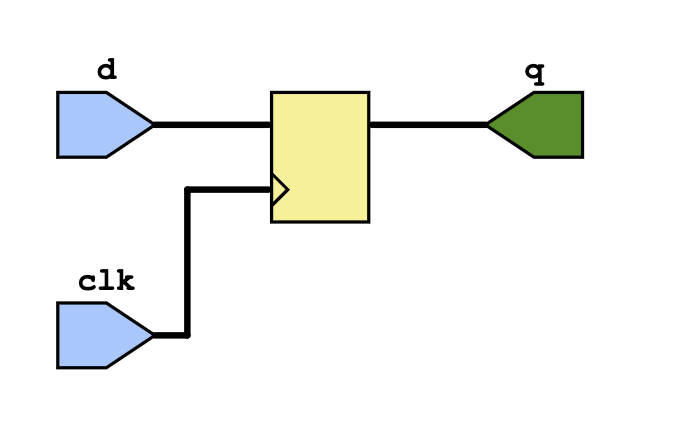
The always block is a fundamental construct used in behavioral modeling to describe how a circuit reacts to changes in its inputs. It allows designers to specify actions that occur when certain conditions are met. For instance, the following example uses an always block to describe a simple flip-flop:
module d_flip_flop(input clk, input d, output reg q);
    always @(posedge clk) begin
        q <= d;  // On rising edge of clk, assign d to q
    end
endmodule
Here, the always block specifies that whenever there’s a positive edge on the clock (posedge clk), the value of d is assigned to the output q. The <= operator is used to indicate non-blocking assignment, which is appropriate for sequential logic like flip-flops.
Schematic of the above verilog code
If Else Statement Example
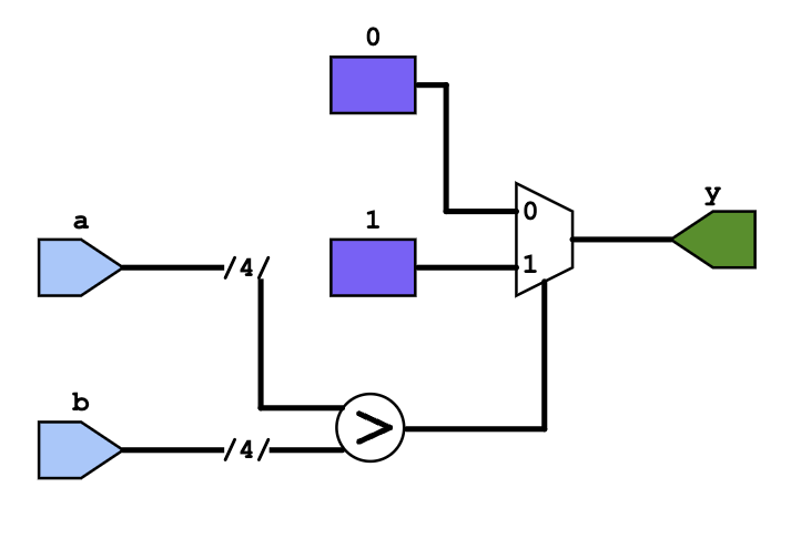
The if-else construct in Verilog allows you to perform conditional logic. Here’s an example where we use if-else to compare two inputs (a and b), and assign an output y based on their comparison:
module comparator(input [3:0] a, input [3:0] b, output reg y);
    always @(a or b) begin  // Trigger on changes to a or b
        if (a > b)
            y = 1;  // If a is greater than b, y is 1
        else
            y = 0;  // If a is not greater, y is 0
    end
endmodule
In this example:
- The
always @(a or b)block specifies that the comparison is triggered when eitheraorbchanges. - The
if-elsestatement comparesaandb, and assigns1toyifais greater thanb; otherwise, it assigns0.
Schematic of the above verilog code
Case Statement Example
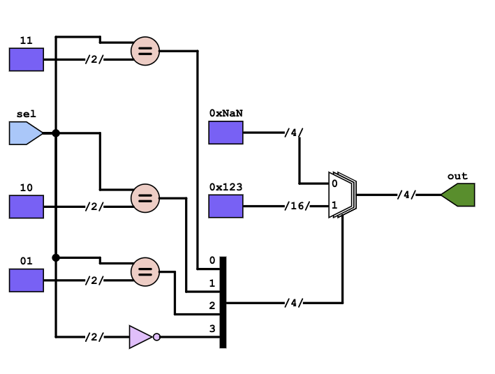
The case statement is useful for handling multiple possible conditions based on a signal’s value. Here’s an example where we use a case statement to set different values of the out signal based on the selection input sel:
module mux(input [1:0] sel, output reg [3:0] out);
    always @(sel) begin
        case(sel)
            2'b00: out = 4'b0000;  // If sel is 00, set out to 0000
            2'b01: out = 4'b0001;  // If sel is 01, set out to 0001
            2'b10: out = 4'b0010;  // If sel is 10, set out to 0010
            2'b11: out = 4'b0011;  // If sel is 11, set out to 0011
            default: out = 4'bxxxx; // Default case to handle undefined values
        endcase
    end
endmodule
In this example:
- The
case(sel)statement checks the value of theselinput, which is 2 bits wide. - Depending on the value of
sel, it assigns a specific 4-bit value to the outputout. - The
defaultcase is used to assign an undefined value (4'bxxxx) ifseltakes a value other than00,01,10, or11.
Schematic of the above verilog code
Register Transfer Level (RTL) Abstraction
Register Transfer Level (RTL) abstraction focuses on how data is transferred between registers and how operations are performed on that data. RTL modeling in Verilog provides a mid-level abstraction of digital circuit behavior, capturing both sequential and combinational logic components.
Introduction to RTL Modeling in Verilog
In RTL, the design is represented by registers and the data transfer between them, alongside the operations that occur on the data. Verilog is commonly used to describe RTL designs with respect to clocked processes, where data is moved synchronously based on the clock signal. RTL abstraction provides a clear understanding of the circuit’s functionality and is widely used in synthesizable designs.
Representation of Data Flow Between Registers
At the RTL level, data transfer between registers is central to the design. Each register holds data, and operations on that data are usually performed in a clocked process. Data flow can be represented through sequential assignments and combinational logic that controls how the data is processed.
Usage of Clocked Processes and Combinational Logic
Clocked processes (i.e., flip-flops or registers) store data on a clock edge, while combinational logic determines how data is modified before it is passed to the next register.
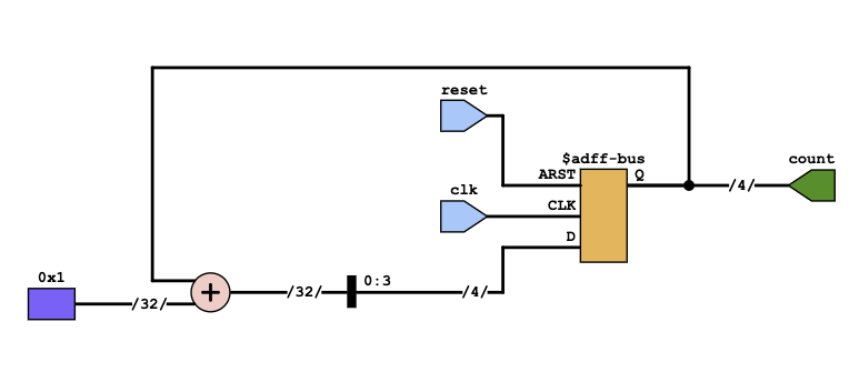
Here’s an example of an RTL description of a 4-bit counter:
module counter(input clk, input reset, output reg [3:0] count);
    always @(posedge clk or posedge reset) begin
        if (reset)
            count <= 4'b0000;  // Reset the counter to 0
        else
            count <= count + 1;  // Increment the counter on each clock cycle
    end
endmodule
In this example:
- The counter’s value is stored in the
countregister. - On each positive edge of
clk, the value ofcountis incremented, or it is reset to0ifresetis high. - The operation is defined in terms of clock cycles, making it suitable for synthesis in hardware.
Here is the Schematic of the above code
Gate-Level Abstraction
Gate-level abstraction involves modeling circuits at a level where components are described using logic gates like AND, OR, NOT, etc. Unlike RTL, which focuses on registers and data flow, gate-level modeling describes the structural components that make up the circuit. Gate-level abstraction is typically used after synthesis or for post-synthesis verification.
Description of Gate-Level Modeling in Verilog
At the gate level, Verilog uses primitive gates to represent the logic in the design. This level provides a more detailed view of the circuit, describing how the gates interact to produce the desired output. Each gate performs a specific logical operation on the inputs to produce a corresponding output.
Focus on Structural Representation of Circuits Using Logic Gates
In gate-level modeling, the design is represented by instances of logic gates such as AND, OR, NAND, NOR, etc., and how they are interconnected to form complex circuits. This is typically used after synthesis, where higher-level RTL code has been converted into a netlist of gates.
Application: Post-Synthesis Verification and Simulation
Gate-level simulation is an essential step in verifying the functionality of the design after it has been synthesized. It helps to ensure that the design behaves as expected at the structural level and that there are no issues related to timing or gate interconnectivity.
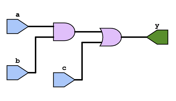
Here’s an example of a simple AND gate and OR gate circuit at the gate level:
module and_or_gate(input a, input b, input c, output y);
    wire w1;

    and(w1, a, b);    // AND gate
    or(y, w1, c);     // OR gate
endmodule
In this example:
- The
andprimitive implements the AND gate betweenaandb. - The
orprimitive implements the OR gate using the output of the AND gate (w1) and inputc. - The gate-level description focuses on how the logic gates are connected to create the desired behavior.
Here is the schematic of the above code
Comparison of Abstraction Layers
Each abstraction level in digital design offers distinct benefits and is suited for different phases of the design process. Understanding when and why to use each abstraction level is essential for efficient design flow.
Key Differences in Focus, Complexity, and Usage
- Behavioral Abstraction:
- Focus: Describes what the design does without specifying how it is implemented.
- Complexity: High-level, abstract, and less detailed.
- Usage: Useful for quick prototyping and high-level design exploration, focusing on functionality.
- Register Transfer Level (RTL) Abstraction:
- Focus: Describes how data is transferred between registers and the operations performed.
- Complexity: More detailed than behavioral abstraction, as it includes registers and data flow.
- Usage: The most common abstraction for synthesizable hardware; directly maps to hardware components like flip-flops and registers.
- Gate-Level Abstraction:
- Focus: Describes the hardware at the logic gate level.
- Complexity: Most detailed, describing the physical gates and their interconnections.
- Usage: Used for post-synthesis verification, to check the exact gate-level implementation of the design.
When to Use Each Abstraction Level in a Design Flow
- Behavioral abstraction is useful during the early stages of design when the goal is to explore different design ideas and focus on high-level functionality. It’s ideal for designing algorithms and defining system behavior.
- RTL abstraction is typically used in the middle stages of design when the focus shifts from high-level behavior to hardware implementation. It is the most common abstraction for designing synthesizable digital circuits and is used during simulation and synthesis.
- Gate-level abstraction comes into play after synthesis, where the design is mapped onto actual hardware gates. It is important for detailed verification, timing analysis, and ensuring that the synthesized design meets the required specifications at the gate level.
Importance of Abstraction in Verilog-Based Design
Abstraction is the cornerstone of modern digital design, enabling engineers to approach complex systems methodically by breaking them into manageable components. In Verilog-based design, abstraction facilitates the creation, verification, and synthesis of hardware designs while ensuring scalability and performance.
Enabling Efficient Design, Verification, and Synthesis
Abstraction levels—behavioral, RTL, and gate-level—serve distinct purposes in the design process. Each layer isolates complexity, allowing designers to focus on specific aspects of the system:
- Design: Behavioral abstraction allows rapid prototyping and functional exploration, while RTL abstraction ensures the design is ready for synthesis into physical hardware.
- Verification: Each abstraction level is verified to ensure correctness before moving to the next. Behavioral tests focus on functionality, RTL tests check register-level correctness, and gate-level tests validate the final hardware implementation.
- Synthesis: RTL designs are translated into hardware through synthesis, where the abstraction is critical to map high-level functionality into an optimized gate-level structure.
Impact on Hardware Performance, Scalability, and Debugging
- Performance: Each abstraction layer contributes to performance optimization. Behavioral models help identify high-level bottlenecks, while RTL and gate-level models enable fine-grained optimization for speed and power.
- Scalability: Modular abstraction supports the development of complex systems by enabling reusability and hierarchical design.
- Debugging: Debugging at higher abstraction levels allows engineers to locate and fix issues early in the design process, reducing costly iterations at the gate or physical levels.
Conclusion
The abstraction levels in Verilog—behavioral, RTL, and gate-level—form the foundation of efficient and structured digital design. Each level serves a unique purpose, from exploring high-level functionality to creating a detailed hardware blueprint, enabling a seamless transition from concept to implementation.
Mastering all three abstraction layers is essential for any hardware designer. Behavioral abstraction allows for rapid prototyping, RTL ensures logical correctness and readiness for synthesis, and gate-level abstraction enables a precise representation of the hardware for verification and post-synthesis optimization.
Understanding the importance of these abstraction levels not only enhances the design process but also ensures scalability, performance, and effective debugging. By applying these principles in practical scenarios, designers can create reliable, high-performing systems that meet the demands of modern electronics.
Abstraction is more than just a method—it’s a mindset that drives innovation in hardware design, empowering designers to tackle increasing complexities while maintaining clarity and focus. As technology advances, the ability to effectively navigate these abstraction levels will remain a critical skill in the evolution of digital systems.
I’m an electrical engineer and chip designer pursuing a Master’s in Electrical Engineering at The University of Texas at Dallas. Passionate about digital design, I created Logic Flick to simplify complex concepts in Verilog, SystemVerilog, and UVM. Join me on this electrifying journey as we explore the world of digital electronics together!