
Data types in Verilog are fundamental building blocks that define how signals are represented, manipulated, and propagated in digital hardware designs. Understanding these data types is essential for creating efficient, error-free simulations and synthesizable hardware designs. Choosing the correct data type can significantly impact a circuit’s behavior during both simulation and synthesis, making it a cornerstone for beginners diving into Verilog.
This guide aims to provide a detailed explanation of the core Verilog data types, including their definitions, roles, and practical examples. Each concept is paired with a complete design and testbench implementation to ensure that beginners can simulate the designs and visualize the results.
What are Verilog Data Types?
Verilog data types describe the nature and behavior of variables and signals in hardware designs. They define whether a signal represents a physical wire connection, stores a value, or interacts with other signals.
- Definition: Data types are constructs that specify how a signal or variable behaves and interacts within a circuit.
- Role: They help designers accurately map their hardware designs to HDL, ensuring proper simulation and synthesis.
Core Verilog Data Types
wire
The wire data type is the most basic and widely used in Verilog. It represents physical connections in combinational logic circuits. A wire is continuously driven by its source and reflects any changes in the source’s value instantaneously.
- Usage: Ideal for connecting gates, modules, and continuous assignments.
- Key Characteristics:
- Does not store data.
- Must be driven by a continuous assignment or module output.
Design Example Using wire:
module wire_example(
input wire a, b, // Two inputs
output wire out // Output
);
assign out = a & b; // AND operation
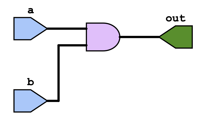
endmoduleHere is the schematic of the above design
Testbench for wire_example:
module tb_wire_example;
    reg a, b;              // Inputs for the testbench
    wire out;              // Output wire

    // Instantiate the design
    wire_example uut (
        .a(a),
        .b(b),
        .out(out)
    );

    initial begin
        $monitor("Time=%0t | a=%b b=%b | out=%b", $time, a, b, out);
        a = 0; b = 0; #10;
        a = 0; b = 1; #10;
        a = 1; b = 0; #10;
        a = 1; b = 1; #10;
        $finish;
    end
endmodule
The above example is a simple AND gate that shows the working of wire data type and note that it doesn’t store any data its just wire connected that drives output for the given inputs.
Output of the code
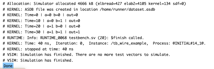
I suggest you to try it out yourself this way you can understand it in a better manner.
reg
The reg data type is used to store values and is commonly utilized in sequential logic and procedural blocks such as always and initial. Unlike wire, a reg holds its value until it is explicitly updated.
- Usage: Used in flip-flops, counters, and state machines.
- Key Characteristics:
- Synthesizable for storage elements.
- Can only be updated inside procedural blocks.
Design Example Using reg:
module reg_example(
    input wire clk, reset,   // Clock and reset signals
    output reg [3:0] count   // 4-bit counter
);
    always @(posedge clk or posedge reset) begin
        if (reset)
            count <= 4'b0000;   // Reset counter
        else
            count <= count + 1; // Increment counter
    end
endmodule
Schematic of the above design that demonstrates the working of verilog data type reg
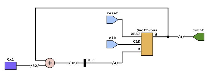
Whenever you declare a reg data type in verilog you are basically using a flipflop to store the data. If you could see the above schematic it includes a flipflop to store the value of 4-bit count variable as we have declared in the module port list.
Testbench for reg_example:
module tb_reg_example;
reg clk, reset; // Clock and reset signals
wire [3:0] count; // 4-bit counter output
// Instantiate the design
reg_example uut (
.clk(clk),
.reset(reset),
.count(count)
);
// Generate clock signal
initial clk = 0;
always #5 clk = ~clk;
initial begin
$monitor("Time=%0t | reset=%b | count=%b", $time, reset, count);
reset = 1; #10;
reset = 0; #50;
reset = 1; #10;
$finish;
end
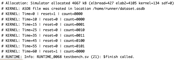
endmoduleOutput simulation
There is another interesting data type that is called tri data type in verilog that we will discuss ahead.
tri
The tri data type is used to model tri-state buffers, which allow a signal to be in one of three states: logic 0, logic 1, or high-impedance (Z). This is useful for shared bus systems.
- Usage: Used in tri-state logic and shared buses.
- Key Characteristics:
- Behaves like
wirebut supports high-impedance states. - Requires careful design to avoid contention on the bus.
- Behaves like
Design Example Using tri:
module tri_example(
    input wire enable, data_in,  // Enable signal and data input
    output tri data_out          // Tri-state output
);
    assign data_out = enable ? data_in : 1'bz; // High-impedance when disabled
endmodule
Here is the schematic of the above verilog code that uses tri data type
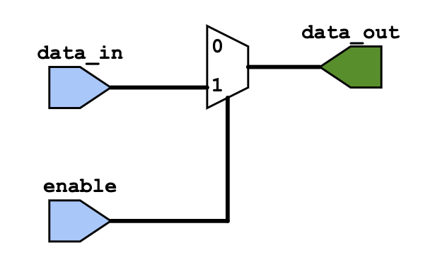
The above code is the combinational circuit. The tri data type in verilog behaves similar to wire data type the only difference is it can also detect the high impedance state meaning its an open wire basically.
Here is the test bench to test the above circuit and with this you will be able to relate how its different from the wire data type
module tb_tri_example;
    reg enable, data_in;    // Inputs
    wire data_out;          // Tri-state output

    // Instantiate the design
    tri_example uut (
        .enable(enable),
        .data_in(data_in),
        .data_out(data_out)
    );

    initial begin
        $monitor("Time=%0t | enable=%b data_in=%b | data_out=%b", $time, enable, data_in, data_out);
        enable = 0; data_in = 0; #10;
        enable = 0; data_in = 1; #10;
        enable = 1; data_in = 0; #10;
        enable = 1; data_in = 1; #10;
        $finish;
    end
endmodule
Output simulation
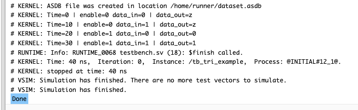
If you observe the output before asserting the enable the data_out is z which means it was basically an open wire.
Other Data Types
supply0 and supply1
These data types represent constant logic levels:
supply0: Represents ground (logic 0).supply1: Represents power (logic 1).
Example:
wire gnd = 1'b0;  // Equivalent to supply0
wire vcc = 1'b1;  // Equivalent to supply1
wand and wor
These are wired-AND and wired-OR net types, respectively. They are used for situations where multiple drivers are connected to a single signal.
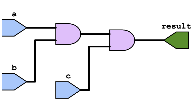
module wand_example(
    input wire a, b, c,
    output wand result
);
    assign result = a & b & c; // Wired-AND behavior
endmodule
Schematic of the above code
Comparison: wire vs. reg
Key Differences in Functionality and Use Cases
wire:
- Used to represent physical connections in combinational logic.
- Passes values that are driven by continuous assignments or module ports.
- Cannot retain values and must be continuously driven.
reg:
- Holds values and is used within procedural blocks (
alwaysorinitial). - Commonly used in sequential logic to model flip-flops and latches.
- Can retain values across simulation time steps.
| Feature | wire | reg |
|---|---|---|
| Usage | Combinational logic | Sequential logic |
| Value Retention | No | Yes |
| Declaration Context | Continuous assignments | Procedural blocks |
Advanced Data Types in Verilog
Vectors
Vectors are multi-bit wires or registers, commonly used to represent buses.
Syntax:
wire [3:0] bus; // 4-bit wire
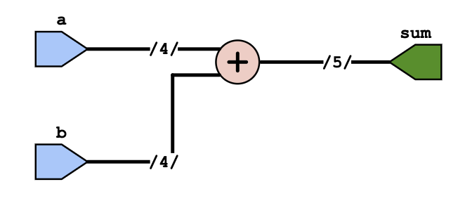
reg [7:0] data; // 8-bit registerExample: 4-bit Adder Using Vectors
module vector_example (
    input [3:0] a,
    input [3:0] b,
    output [4:0] sum
);
    assign sum = a + b;
endmodule
Schematic of the above verilog code
Testbench code to test the above circuit
module tb_vector_example;
reg [3:0] a, b;
wire [4:0] sum;
vector_example uut (
.a(a),
.b(b),
.sum(sum)
);
initial begin
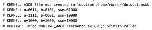
$monitor("a=%b, b=%b, sum=%b", a, b, sum);
a = 4'b0011; b = 4'b0101; // 3 + 5
#10 a = 4'b1111; b = 4'b0001; // 15 + 1
#10 a = 4'b1000; b = 4'b1000; // 8 + 8
#10 $finish;
end
endmoduleOutput simulation
Arrays
Arrays group multiple elements of the same data type, often used to represent memory.
Syntax:
reg [7:0] memory [0:15]; // 16x8 memory arrayExample: Memory Write and Read
Design code below
module array_example (
    input [1:0] address,
    output reg [7:0] data_out
);
    reg [7:0] memory [0:3]; // Memory array

    initial begin
        // Initialize memory with some values
        memory[0] = 8'hAA;
        memory[1] = 8'hBB;
        memory[2] = 8'hCC;
        memory[3] = 8'hDD;
    end

    always @(*) begin
        // Read data from memory based on address
        data_out <= memory[address];
    end
endmodule
Here is the test bench code
module tb_array_example;
    reg [1:0] address;       // Address to select memory location
    wire [7:0] data_out;     // Data output from memory

    // Instantiate the array_example module
    array_example uut (
        .address(address),
        .data_out(data_out)
    );

    initial begin
        $monitor("At time %0t: Address=%b, Data=%h", $time, address, data_out);

        // Test various addresses
        address = 2'b00; #10;
        address = 2'b01; #10;
        address = 2'b10; #10;
        address = 2'b11; #10;

        $finish; // End the simulation
    end
endmodule
Output simulation

User-Defined Data Types
User-defined types help improve readability and reusability using typedef.
Syntax:
typedef reg [7:0] byte;
byte data;
Example: Using typedef
Design code
typedef reg [15:0] word; // Define a new type 'word'
module typedef_example (
output word data // Use 'word' as the type for the output
);
initial begin
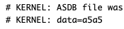
data = 16'hA5A5; // Assign a value to the output
end
endmodule
Test bench code
module tb_typedef_example;
    wire [15:0] data;

    // Instantiate the design
    typedef_example uut (
        .data(data)
    );

    initial begin
        $monitor("data=%h", data); // Monitor the output
        #10; // Wait for simulation
        $finish;
    end
endmodule
Output
Parameters and Constants
Parameters are used to declare constants that can be overridden during module instantiation.
Syntax:
parameter WIDTH = 8;
reg [WIDTH-1:0] data;
Example: Parameterized Module
module parameter_example #(parameter WIDTH = 8) (
    input [WIDTH-1:0] a,
    input [WIDTH-1:0] b,
    output [WIDTH-1:0] sum
);
    assign sum = a + b;
endmodule
Here is the test bench to test the above circuit
module tb_parameter_example;
reg [7:0] a, b;
wire [7:0] sum;
parameter_example #(.WIDTH(8)) uut (
.a(a),
.b(b),
.sum(sum)
);
initial begin
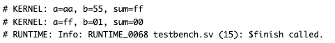
$monitor("a=%h, b=%h, sum=%h", a, b, sum);
a = 8'hAA; b = 8'h55;
#10 a = 8'hFF; b = 8'h01;
#10 $finish;
end
endmoduleOutput
Common Pitfalls and Best Practices
Common Pitfalls:
- Mixing
wireandreg: Misusingwirein procedural blocks orregin continuous assignments. - Improper Initialization: Forgetting to initialize
regvariables, leading to undefined behavior. - Overusing
assign: Assigning values in procedural blocks instead of usingalways.
Best Practices:
- Comment Code: Add comments for complex logic to improve readability.
- Use Descriptive Names: Avoid using short or unclear variable names.
- Simulate Thoroughly: Use comprehensive testbenches to verify all possible cases.
I’m an electrical engineer and chip designer pursuing a Master’s in Electrical Engineering at The University of Texas at Dallas. Passionate about digital design, I created Logic Flick to simplify complex concepts in Verilog, SystemVerilog, and UVM. Join me on this electrifying journey as we explore the world of digital electronics together!