
Verilog is one of the most widely used hardware description languages (HDLs) for designing and modeling digital circuits. Its primary use is to define the behavior, structure, and functionality of hardware systems. For beginners, mastering the correct syntax of Verilog is a fundamental step in becoming proficient at digital hardware design. Verilog syntax is the foundation of all Verilog-based designs, and understanding how to structure and write code correctly is essential for creating efficient and error-free hardware systems. In this guide, we will break down essential Verilog syntax elements to help you get started, ensuring that your designs are not only functional but also clean and maintainable.
Comments in Verilog
One of the first and most important aspects of any programming language is the ability to document the code, and Verilog is no different. Comments help describe the functionality of the code and provide context, making it easier for others to understand your design. In Verilog, there are two primary ways to write comments: single-line comments and multi-line comments.
Single-Line Comments
Single-line comments are used for short explanations or notes about the code. They are written using the // syntax. Anything following // on that line is considered a comment and is ignored by the Verilog compiler.
Here is an example
// This is a single-line comment
assign sum = a + b; // Sum the values of a and b
Single-line comments are great for brief descriptions or annotations next to specific lines of code. They help clarify the purpose of a line or block of code.
Multi-Line Comments
When you need to explain a larger block of code or write a more detailed description, multi-line comments come in handy. These comments are enclosed by /* at the beginning and */ at the end. Multi-line comments can span multiple lines, making them ideal for documenting complex functions or modules.
Here is an example of verilog multiline comment
/*
  This is a multi-line comment.
  It can span multiple lines and is useful for providing
  detailed descriptions or explanations.
*/
assign product = a * b;nm
Multi-line comments can also be helpful when temporarily disabling code during debugging. You can comment out a block of code and restore it later without affecting the rest of your design.
Best Practices for Commenting
- Be Clear and Concise: Comments should explain why something is done, not what is done. Avoid redundant comments that describe the obvious.
- Use Comments Liberally: Especially for complex algorithms or components, use comments to guide the reader through your thought process.
- Update Comments: Ensure your comments are updated whenever you change the associated code. Outdated comments can be more harmful than helpful.
Following these practices will not only help you communicate your design effectively but also make it easier for others to collaborate on or maintain your code.
Whitespace and Formatting
While whitespace doesn’t affect the functionality of Verilog code, it plays a crucial role in making your code readable and organized. Proper formatting ensures that your Verilog code is easy to understand, maintain, and debug.
The Role of Whitespace
Whitespace in Verilog includes spaces, tabs, and line breaks. While these elements don’t impact the functionality of the code, they significantly affect how easily a human can read and understand it. Proper use of whitespace helps separate logical sections of the code, making it clearer and less cluttered.
For example, consider the following two blocks of Verilog code:
Without Proper Whitespace:
module simple_adder(input a,b,c,d,e,f,g,h,i,j,k,l,m,n,o,p,q,r,s,t,u,v,w,x,y,z,input x1,y1,z1);
assign out1=(a&b)|c;
assign out2=(c&d)|e;
assign out3=(f&g)|h;
assign out4=(i&j)|k;
endmodule
With Proper Whitespace:
module simple_adder(
    input a, b, c, d, e, f, g, h,
    input i, j, k, l, m, n, o, p,
    input q, r, s, t, u, v, w, x,
    input y, z, x1, y1, z1
);

    assign out1 = (a & b) | c;
    assign out2 = (c & d) | e;
    assign out3 = (f & g) | h;
    assign out4 = (i & j) | k;

endmodule
The second example is much easier to read and understand. Breaking long lines into smaller segments, aligning inputs, and adding extra spaces between logic operations all contribute to improving the visual structure of the code.
Guidelines for Indentation and Consistent Formatting
Indentation is crucial when working with Verilog code, especially as designs grow in complexity. A consistent indentation style makes it easier to trace logic flow and understand how different parts of the code are related.
Here are some guidelines for proper indentation and formatting:
- Use Consistent Indentation: Whether you use spaces or tabs, pick one method and stick to it throughout your codebase. A common convention is to use 2 spaces per indentation level.
- Align Code for Readability: Align related elements like inputs, assignments, and logical operators. This makes it easier to spot patterns and potential issues in the code.
- Separate Blocks Logically: Use blank lines to separate distinct blocks of code (e.g., module declaration, assign statements, procedural blocks). This improves readability and helps organize code into logical sections.
- Caps for Keywords: It’s common to use uppercase letters for Verilog keywords (like
assign,module,input,output) and lowercase for user-defined names. This helps distinguish between built-in Verilog keywords and custom identifiers. - Line Length: Try to keep each line of code under 80 characters. This makes your code more readable, especially when viewing it on different devices or in code editors with fixed-width fonts.
Examples of Good and Bad Formatting Practices
Good Formatting:
module simple_adder (
    input a, b, c, d,
    output sum
);

    assign sum = a + b + c + d;

endmodule
Bad Formatting:
module simple_adder(input a,b,c,d,output sum);assign sum=a+b+c+d;endmoduleThe good formatting example is clean and easy to follow, while the bad formatting example is cluttered and difficult to read, especially for those who might be unfamiliar with the code.
Operators in Verilog
Operators are a vital part of Verilog syntax, providing a means to perform operations on variables and signals. They help define the functionality of your hardware design by enabling arithmetic calculations, logical evaluations, and bit manipulations. This section will detail the different types of operators in Verilog, their precedence, and their usage with examples. Understanding these operators is fundamental for beginners aiming to master Verilog syntax.
Arithmetic Operators
Verilog supports basic arithmetic operations, essential for tasks like addition, subtraction, and more:
%: Modulus (remainder).
+: Addition.
-: Subtraction.
*: Multiplication.
/: Division.
Example: Arithmetic Operators with Testbench
Design Code:
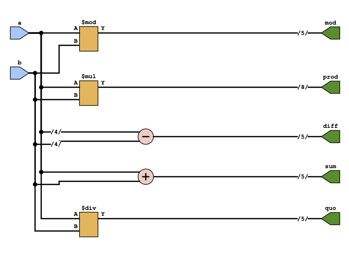
module ArithmeticOps(input [3:0] a, input [3:0] b, output [4:0] sum, output [4:0] diff, output [7:0] prod, output [4:0] quo, output [4:0] mod);
  assign sum = a + b;
  assign diff = a - b;
  assign prod = a * b;
  assign quo = a / b;
  assign mod = a % b;
endmodule
Schematic of the above code
Test Bench
module tb_ArithmeticOps;
reg [3:0] a, b;
wire [4:0] sum, diff, quo, mod;
wire [7:0] prod;
ArithmeticOps uut (a, b, sum, diff, prod, quo, mod);
initial begin
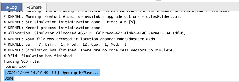
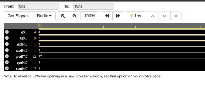
a = 4; b = 3;
#10;
$display("Sum: %d, Diff: %d, Prod: %d, Quo: %d, Mod: %d", sum, diff, prod, quo, mod);
end
endmoduleOutput
Logical Operators
Logical operators evaluate conditions and return boolean results.
&&(Logical AND): Returnstrue(1) if both operands aretrue. Example:x && y.||(Logical OR): Returnstrueif at least one operand istrue. Example:x || y.!(Logical NOT): Negates the operand. Example:!x.
Design Code:
Logical operations evaluate the conditions x && y, x || y, and !x. The results are stored in respective outputs.
module LogicalOps(input x, input y, output and_out, output or_out, output not_out);
  assign and_out = x && y;
  assign or_out = x || y;
  assign not_out = !x;
endmodule
TestBench
// Code your testbench here
// or browse Examples
module tb_LogicalOps;
reg x, y;
wire and_out, or_out, not_out;
LogicalOps uut (x, y, and_out, or_out, not_out);
initial begin
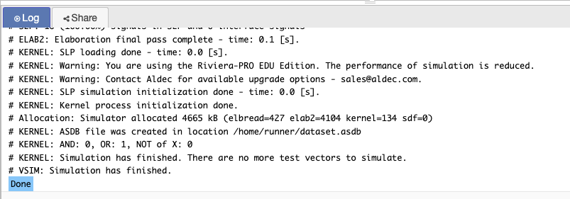
x = 1; y = 0;
#10;
$display("AND: %b, OR: %b, NOT of X: %b", and_out, or_out, not_out);
end
endmoduleOutput
Relational Operators
Relational operators compare two values and return a boolean result.
==(Equal To): Checks if two values are equal.!=(Not Equal To): Checks if two values are not equal.<,>,<=,>=: Compare numerical values to check their relative magnitudes.
Design Code:
In the provided example:
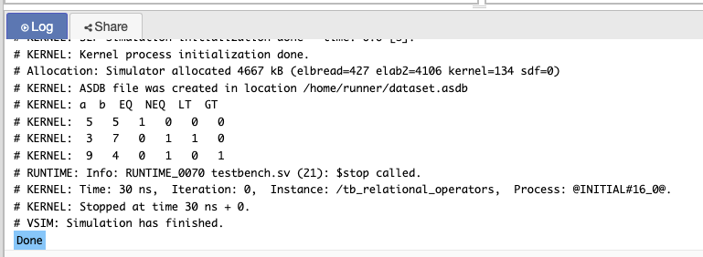
module relational_operators(
    input [3:0] a,
    input [3:0] b,
    output eq,
    output neq,
    output lt,
    output gt
);
    assign eq = (a == b);
    assign neq = (a != b);
    assign lt = (a < b);
    assign gt = (a > b);
endmodule
Test bench code
module tb_relational_operators;
    reg [3:0] a, b;
    wire eq, neq, lt, gt;

    relational_operators uut (
        .a(a),
        .b(b),
        .eq(eq),
        .neq(neq),
        .lt(lt),
        .gt(gt)
    );

    initial begin
        $display("a  b  EQ  NEQ  LT  GT");
        a = 4'd5; b = 4'd5; #10; $display("%d  %d   %b   %b   %b   %b", a, b, eq, neq, lt, gt);
        a = 4'd3; b = 4'd7; #10; $display("%d  %d   %b   %b   %b   %b", a, b, eq, neq, lt, gt);
        a = 4'd9; b = 4'd4; #10; $display("%d  %d   %b   %b   %b   %b", a, b, eq, neq, lt, gt);
        $stop;
    end
endmodule
Output
Bitwise Operators
Bitwise operators perform bit-level manipulation between operands.
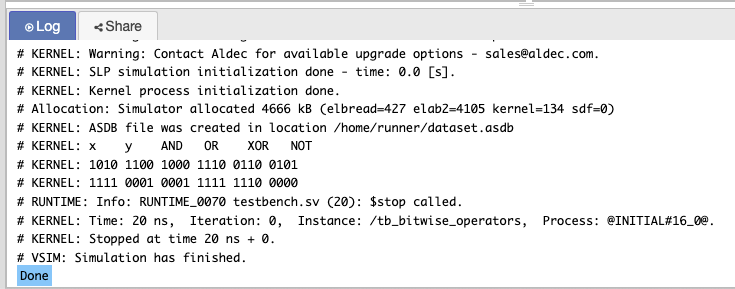
&(Bitwise AND): Performs AND on each bit. Example:1010 & 1100 = 1000.|(Bitwise OR): Performs OR on each bit. Example:1010 | 1100 = 1110.^(Bitwise XOR): Performs XOR on each bit. Example:1010 ^ 1100 = 0110.~(Bitwise NOT): Inverts each bit. Example:~1010 = 0101.
Design code
module bitwise_operators(
    input [3:0] x,
    input [3:0] y,
    output [3:0] and_out,
    output [3:0] or_out,
    output [3:0] xor_out,
    output [3:0] not_out
);
    assign and_out = x & y;
    assign or_out = x | y;
    assign xor_out = x ^ y;
    assign not_out = ~x;
endmodule
Testbench
module tb_bitwise_operators;
    reg [3:0] x, y;
    wire [3:0] and_out, or_out, xor_out, not_out;

    bitwise_operators uut (
        .x(x),
        .y(y),
        .and_out(and_out),
        .or_out(or_out),
        .xor_out(xor_out),
        .not_out(not_out)
    );

    initial begin
        $display("x    y    AND   OR    XOR   NOT");
        x = 4'b1010; y = 4'b1100; #10; $display("%b %b %b %b %b %b", x, y, and_out, or_out, xor_out, not_out);
        x = 4'b1111; y = 4'b0001; #10; $display("%b %b %b %b %b %b", x, y, and_out, or_out, xor_out, not_out);
        $stop;
    end
endmodule
Output
Reduction Operators in Verilog
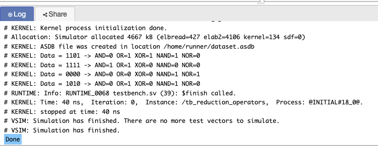
Verilog provides reduction operators that allow you to perform bitwise operations across all the bits in a vector. These operators are useful for aggregating results from a bit vector into a single Boolean value.
Design Code
module reduction_operators (
    input [3:0] data,  // 4-bit input data
    output and_result,  // AND reduction result
    output or_result,   // OR reduction result
    output xor_result,  // XOR reduction result
    output nand_result, // NAND reduction result
    output nor_result   // NOR reduction result
);

// AND reduction: returns 1 if all bits are 1, else 0
assign and_result = &data;

// OR reduction: returns 1 if any bit is 1, else 0
assign or_result = |data;

// XOR reduction: returns 1 if there is an odd number of 1's, else 0
assign xor_result = ^data;

// NAND reduction: returns 1 if not all bits are 1
assign nand_result = ~&data;

// NOR reduction: returns 1 if all bits are 0, else 0
assign nor_result = ~|data;

endmodule
TestBench code
module tb_reduction_operators;

// Testbench signals
reg [3:0] data;
wire and_result, or_result, xor_result, nand_result, nor_result;

// Instantiate the design module
reduction_operators uut (
    .data(data),
    .and_result(and_result),
    .or_result(or_result),
    .xor_result(xor_result),
    .nand_result(nand_result),
    .nor_result(nor_result)
);

// Stimulus generation
initial begin
    // Test case 1: data = 4'b1101
    data = 4'b1101;
    #10;
    $display("Data = %b -> AND=%b OR=%b XOR=%b NAND=%b NOR=%b", data, and_result, or_result, xor_result, nand_result, nor_result);

    // Test case 2: data = 4'b1111
    data = 4'b1111;
    #10;
    $display("Data = %b -> AND=%b OR=%b XOR=%b NAND=%b NOR=%b", data, and_result, or_result, xor_result, nand_result, nor_result);

    // Test case 3: data = 4'b0000
    data = 4'b0000;
    #10;
    $display("Data = %b -> AND=%b OR=%b XOR=%b NAND=%b NOR=%b", data, and_result, or_result, xor_result, nand_result, nor_result);

    // Test case 4: data = 4'b1010
    data = 4'b1010;
    #10;
    $display("Data = %b -> AND=%b OR=%b XOR=%b NAND=%b NOR=%b", data, and_result, or_result, xor_result, nand_result, nor_result);

    $finish;
end

endmodule
Output
Operator Precedence and Associativity in Verilog
In Verilog, operator precedence determines the order in which operations are performed. Understanding the precedence and associativity of operators is essential for writing clear and correct Verilog code.
Operator Precedence in Verilog
Operators in Verilog are executed in a specific order, from highest to lowest precedence. Here’s a simplified order of precedence:
- Parentheses
(): Used to group expressions and override default precedence. - Unary Operators:
!,~,+,-(e.g., negation and bitwise inversion). - Multiplicative Operators:
*,/,%(multiplication, division, and modulo). - Additive Operators:
+,-(addition and subtraction). - Shift Operators:
<<,>>(left and right shifts). - Relational Operators:
==,!=,<,>,<=,>=(comparisons). - Logical Operators:
&&,||,!(AND, OR, NOT). - Bitwise Operators:
&,|,^,~(AND, OR, XOR, and bitwise NOT).
Operator Associativity
- Left-to-Right Associativity: Most operators, such as the bitwise and logical operators, associate from left to right. For example, in the expression
a + b - c, the addition and subtraction are performed from left to right. - Right-to-Left Associativity: The assignment operators (
=) and conditional (?:) operator have right-to-left associativity. For example, in the expressiona = b = c;,b = cis evaluated first.
wire [3:0] a, b, c;
assign a = b + c * 2;  // Multiplication happens before addition due to precedence
Number Formats in Verilog
Understanding number formats in Verilog syntax is fundamental when dealing with digital design, as they provide a way to define how numbers are represented, manipulated, and processed in hardware. In Verilog, numbers can be represented in various formats such as binary, octal, decimal, and hexadecimal, with specific ways to define their size, signed/unsigned nature, and how negative numbers are represented. This section will cover the essential aspects of Verilog syntax related to number formats, including sized numbers, unsized numbers, radix formats, negative numbers, and string representations.
Sized Numbers in Verilog
In Verilog, sized numbers allow you to specify the exact number of bits for a particular variable. This is crucial for ensuring that signals or variables are represented with the desired precision and correctly fit into the designed hardware.
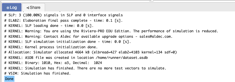
A sized number consists of the bit-width followed by the number, specified in a particular base (binary, octal, decimal, or hexadecimal).
Design code
module sized_numbers;

// Defining sized numbers
reg [3:0] binary_num;    // 4-bit binary number
reg [7:0] hex_num;       // 8-bit hexadecimal number
reg [15:0] dec_num;      // 16-bit decimal number

initial begin
    // Assigning values using binary, hexadecimal, and decimal
    binary_num = 4'b1010;   // Binary representation: 4-bit
    hex_num = 8'hA3;        // Hexadecimal representation: 8-bit
    dec_num = 16'd1024;     // Decimal representation: 16-bit

    // Displaying values
    $display("Binary: %b, Hex: %h, Decimal: %d", binary_num, hex_num, dec_num);
end

endmodule
Output
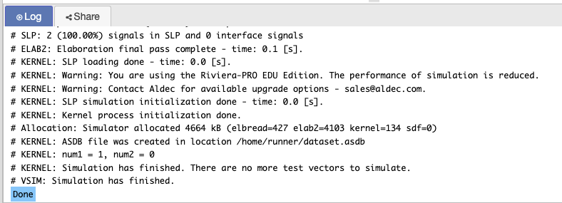
Unsized Numbers in Verilog
Unsized numbers refer to numbers whose bit-width is not explicitly defined. In Verilog, if you do not specify a size for a number, it will default to 32 bits.
Design Code Example:
module unsized_numbers;

// Define unsized numbers
reg num1, num2;

initial begin
    // Assign values to unsized numbers
    num1 = 1'b1;  // A 1-bit value
    num2 = 1'b0;  // Another 1-bit value

    // Display values
    $display("num1 = %b, num2 = %b", num1, num2);
end

endmodule
Output
Explanation:
- Unsized numbers do not specify bit-width, and they will default to 32 bits unless otherwise specified.
- The testbench checks how unsized numbers behave with 1-bit inputs and displays the results.
Radix Formats in Verilog
Verilog provides the ability to specify the radix (base) of the numbers being used. You can represent numbers in binary (b), octal (o), decimal (d), or hexadecimal (h) formats. Each of these radices has its specific use cases in hardware design and simulation.
Design Code Example for Radix Formats:
module radix_formats;

// Defining numbers in different radices
reg [3:0] bin_num;
reg [3:0] oct_num;
reg [3:0] dec_num;
reg [3:0] hex_num;

initial begin
    // Assign values in binary, octal, decimal, and hexadecimal
    bin_num = 4'b1100;   // Binary: 1100
    oct_num = 4'o14;     // Octal: 14 (equivalent to decimal 12)
    dec_num = 4'd12;     // Decimal: 12
    hex_num = 4'hC;      // Hexadecimal: C (equivalent to decimal 12)

    // Display the values in various formats
    $display("Binary: %b, Octal: %o, Decimal: %d, Hex: %h", bin_num, oct_num, dec_num, hex_num);
end

endmodule
Output
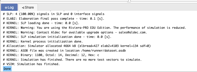
Explanation:
- The design code uses radix formats to assign values in binary, octal, decimal, and hexadecimal formats.
- The testbench initializes the signals and checks how the design behaves with the different formats.
String Representation in Verilog
Verilog allows the use of strings in simulations, which can be particularly useful for debugging and simulation output. However, strings are typically not used in synthesis but rather for simulation purposes only.
Design Code Example for String Representation:
module string_example;

// Defining string variables
string str1;
string str2;

initial begin
    // Assign string values
    str1 = "Hello, Verilog!";
    str2 = "This is a string example.";

    // Display string values
    $display("str1 = %s", str1);
    $display("str2 = %s", str2);
end

endmodule
Output
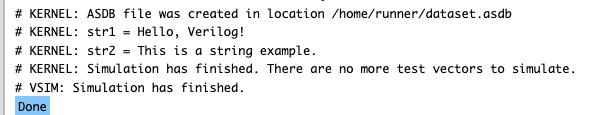
Explanation:
- Strings are initialized using double quotes (
") and can be printed during simulation. - The testbench sets string values and outputs them using the
$displaystatement
Identifiers and Keywords in Verilog
In Verilog syntax, identifiers and keywords are fundamental concepts that define how you name your variables and recognize reserved words in the language. Understanding the rules for naming identifiers and the role of keywords helps avoid common mistakes in hardware description and design.
Identifiers in Verilog
Identifiers are names used to represent various elements in your Verilog code, such as variables, modules, and functions. The rules for naming identifiers are strict to ensure clarity and avoid conflicts.
Rules for Naming Identifiers:
- An identifier must begin with a letter (A-Z or a-z) or an underscore (
_). - After the first character, an identifier can contain letters, digits (0-9), and underscores.
- Verilog is case-sensitive, meaning that
myVar,myvar, andMYVARare all distinct identifiers. - Identifiers must not conflict with reserved keywords (which we’ll cover in the next section).
- Verilog has a limit on identifier length, but most modern tools support lengths of up to 1024 characters.
Valid and Invalid Identifiers:
Valid Identifiers:
my_signal
counter_1
dataIn
_abc
valid123
Invalid Identifiers:
1signal // Cannot start with a digit
my@signal // Cannot contain special characters other than underscore
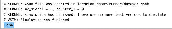
module // 'module' is a reserved keywordDesign code
module identifier_example;
    reg my_signal;   // Valid identifier
    reg counter_1;  // Valid identifier

    initial begin
        my_signal = 1'b1;
        counter_1 = 1'b0;
        $display("my_signal = %b, counter_1 = %b", my_signal, counter_1);
    end
endmodule
Output
Keywords in Verilog
Keywords are reserved words in Verilog syntax that have special meanings. They define the structure and behavior of your code and cannot be used as identifiers for variables, signals, or modules.
Common Verilog Keywords:
- module: Used to define a module in Verilog.
- always: Defines a procedural block that runs on specific events or conditions.
- assign: Used to assign values to nets.
- input: Defines an input signal.
- output: Defines an output signal.
- reg: Defines a variable that stores values.
- wire: Defines a net, which carries signals.
- initial: Specifies the initial behavior in simulation.
Design Code Example Using Keywords:
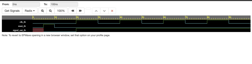
module simple_example(input wire clk, reset, output reg signal_out);
    always @(posedge clk or posedge reset) begin
        if (reset)
            signal_out <= 0;
        else
            signal_out <= 1;
    end
endmodule
Testbench
module tb_simple_example;
    reg clk_tb, reset_tb;
    wire signal_out_tb;

    // Instantiate the design module
    simple_example uut (
        .clk(clk_tb),
        .reset(reset_tb),
        .signal_out(signal_out_tb)
    );

    initial begin
        clk_tb = 0;
        reset_tb = 0;
        #5 reset_tb = 1;
        #5 reset_tb = 0;

        // Generate clock signal
        forever #10 clk_tb = ~clk_tb;
    end

    initial begin
        $monitor("At time %t: signal_out = %b", $time, signal_out_tb);
        #100 $finish;
    end
endmodule
Output simulation waveform
Data Types in Verilog
In Verilog, data types are essential to defining how variables, nets, and other elements are represented and behave during simulation and synthesis. The two main categories of data types in Verilog are net types and variable types, each with distinct characteristics and use cases.
Net Types:
- wire: Used for continuous assignments (e.g.,
assignstatements). - tri: Tri-state net used for modeling high-impedance states (e.g., bus systems).
Variable Types:
- reg: Used for variables that hold values, typically in procedural blocks like
always. - integer: 32-bit signed variable used for whole numbers.
- real: Used for floating-point values in simulations.
- time: Used to store simulation time.
Design Code Example for Data Types:
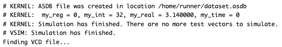
module data_types_example;
   // wire my_wire;      // Net type
    reg my_reg;        // Variable type
    integer my_int;    // Integer type
    real my_real;      // Real type
    time my_time;      // Time type

    initial begin
      //  my_wire = 1'b1;
        my_reg = 1'b0;
        my_int = 32;
        my_real = 3.14;
        my_time = $time;

      $display(" my_reg = %0b, my_int = %0d, my_real = %0f, my_time = %0t",
                   my_reg, my_int, my_real, my_time);
    end
endmodule
Output
Verilog Statements
Verilog statements define the behavior and structure of hardware in both structural and behavioral styles. A solid understanding of these statements helps when designing and simulating digital circuits. In this section, we will cover structural constructs, behavioral constructs, and how to use continuous assignments in Verilog.
Structural Constructs
Structural constructs in Verilog describe how hardware is connected, using lower-level modules, gates, and interconnections. This approach focuses on the physical structure of the system, where the design is described as a collection of interconnected components (such as logic gates, flip-flops, etc.).
Design Code Example (Structural):
module and_gate(input wire A, input wire B, output wire Y);
assign Y = A & B; // AND gate
endmodule
module or_gate(input wire A, input wire B, output wire Y);
assign Y = A | B; // OR gate
endmodule
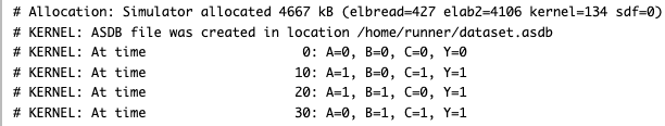
module structural_example(input wire A, input wire B, input wire C, output wire Y);
wire and_out, or_out;
and_gate u1 (A, B, and_out); // AND gate instance
or_gate u2 (and_out, C, or_out); // OR gate instance
assign Y = or_out; // Final output from OR gate
endmodule
Testbench
module tb_structural_example;
    reg A_tb, B_tb, C_tb;
    wire Y_tb;

    // Instantiate the design module
    structural_example uut (
        .A(A_tb),
        .B(B_tb),
        .C(C_tb),
        .Y(Y_tb)
    );

    initial begin
        // Apply test vectors
        A_tb = 0; B_tb = 0; C_tb = 0;
        #10 A_tb = 1; B_tb = 0; C_tb = 1;
        #10 A_tb = 1; B_tb = 1; C_tb = 0;
        #10 A_tb = 0; B_tb = 1; C_tb = 1;
        #10;
        $finish;
    end

    initial begin
        $monitor("At time %t: A=%b, B=%b, C=%b, Y=%b", $time, A_tb, B_tb, C_tb, Y_tb);
    end
endmodule
Output simulation
Behavioral Constructs
Behavioral constructs allow designers to describe the functionality of circuits in a higher-level abstraction. Instead of describing how a circuit is built from gates, you describe what it should do, and the Verilog synthesizer handles the translation to gate-level design.
Procedural Blocks:
alwaysBlock: Thealwaysblock is used for describing behavior that occurs continuously during simulation, triggered by specific signals.alwaysis used to model sequential logic and is sensitive to changes in input signals.- It runs in a loop and executes whenever the sensitivity list changes.
Example (always block):
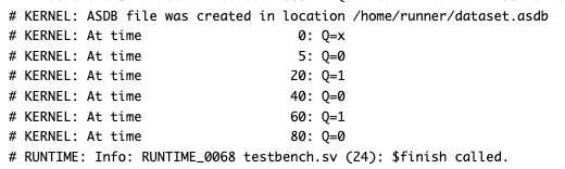
module always_example(input wire clk, input wire reset, output reg Q);
    always @(posedge clk or posedge reset) begin
        if (reset)
            Q <= 0;  // Reset condition
        else
            Q <= ~Q; // Toggle on each clock pulse
    end
endmodule
Testbench code
module tb_always_example;
    reg clk_tb, reset_tb;
    wire Q_tb;

    // Instantiate the design module
    always_example uut (
        .clk(clk_tb),
        .reset(reset_tb),
        .Q(Q_tb)
    );

    initial begin
        // Initialize signals
        clk_tb = 0; reset_tb = 0;
        #5 reset_tb = 1;
        #5 reset_tb = 0;

        // Generate clock signal
        forever #10 clk_tb = ~clk_tb;
    end

    initial begin
        $monitor("At time %t: Q=%b", $time, Q_tb);
        #100 $finish;
    end
endmodule
Ouput
initial Block:
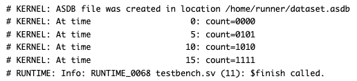
The initial block runs once at the beginning of the simulation. It is often used to initialize variables or apply stimulus to the design.
Example (initial block):
module initial_example(output reg [3:0] count);
    initial begin
        count = 4'b0000;
        #5 count = 4'b0101;
        #5 count = 4'b1010;
        #5 count = 4'b1111;
    end
endmodule
TestBench
module tb_initial_example;
    wire [3:0] count_tb;

    // Instantiate the design module
    initial_example uut (
        .count(count_tb)
    );

    initial begin
        $monitor("At time %t: count=%b", $time, count_tb);
        #20 $finish;
    end
endmodule
Output
Conditional Statements:
if-else and case statements are used for conditional execution in Verilog, allowing you to specify actions depending on the values of inputs.
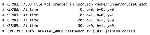
if-else Example:
module if_else_example(input wire a, input wire b, output reg y);
    always @(*) begin
        if (a == 1'b1 && b == 1'b0)
            y = 1'b1;
        else
            y = 1'b0;
    end
endmodule
Testbench Code for if-else Example:
module tb_if_else_example;
    reg a_tb, b_tb;
    wire y_tb;

    // Instantiate the design module
    if_else_example uut (
        .a(a_tb),
        .b(b_tb),
        .y(y_tb)
    );

    initial begin
        a_tb = 0; b_tb = 0;
        #10 a_tb = 1; b_tb = 0;
        #10 a_tb = 1; b_tb = 1;
        #10 a_tb = 0; b_tb = 1;
        #10;
        $finish;
    end

    initial begin
        $monitor("At time %t: a=%b, b=%b, y=%b", $time, a_tb, b_tb, y_tb);
    end
endmodule
Output
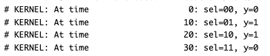
case Example:
module case_example(input wire [1:0] sel, output reg y);
    always @(*) begin
        case(sel)
            2'b00: y = 1'b0;
            2'b01: y = 1'b1;
            2'b10: y = 1'b1;
            2'b11: y = 1'b0;
            default: y = 1'b0;
        endcase
    end
endmodule
Testbench
module tb_case_example;
    reg [1:0] sel_tb;
    wire y_tb;

    // Instantiate the design module
    case_example uut (
        .sel(sel_tb),
        .y(y_tb)
    );

    initial begin
        sel_tb = 2'b00; #10;
        sel_tb = 2'b01; #10;
        sel_tb = 2'b10; #10;
        sel_tb = 2'b11; #10;
        $finish;
    end

    initial begin
        $monitor("At time %t: sel=%b, y=%b", $time, sel_tb, y_tb);
    end
endmodule
Output
Continuous Assignments: Using assign for Combinational Logic
In Verilog, combinational logic can be described using continuous assignments. This is done with the assign keyword, which allows you to continuously drive values onto nets (such as wire) based on the logic described.
Example of Continuous Assignment
The assign statement is used to continuously assign a value to a net. This is typically used for describing simple combinational logic without the need for procedural blocks (always or initial).
Design Code:
module and_gate (
    input wire a, b,  // Inputs for AND gate
    output wire out   // Output of AND gate
);

    assign out = a & b;  // Continuous assignment for AND operation

endmodule
Test Bench code
module tb_and_gate;
    // Testbench for the and_gate module

    reg a, b;  // Declare registers for input signals
    wire out;  // Declare wire for output signal

    // Instantiate the and_gate module
    and_gate uut (
        .a(a),
        .b(b),
        .out(out)
    );

    // Test sequence
    initial begin
        // Monitor output changes
        $monitor("a = %b, b = %b, out = %b", a, b, out);

        // Initialize inputs
        a = 0; b = 0; #10;
        a = 0; b = 1; #10;
        a = 1; b = 0; #10;
        a = 1; b = 1; #10;

        // End simulation
        $finish;
    end
endmodule
Output
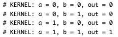
Explanation:
- In the
and_gatemodule, theassignstatement continuously assigns the result of the AND operation to theoutwire. - The testbench (
tb_and_gate) applies various input combinations to test the AND gate’s functionality. - The
$monitorstatement helps us observe the input-output transitions in real-time during simulation.
I’m an electrical engineer and chip designer pursuing a Master’s in Electrical Engineering at The University of Texas at Dallas. Passionate about digital design, I created Logic Flick to simplify complex concepts in Verilog, SystemVerilog, and UVM. Join me on this electrifying journey as we explore the world of digital electronics together!